
Here is a multi year ‘back-burner’ project I’ve been working on.
I got the idea one day to make a sailing canoe. You know the one, South Pacific style, with outrigger and crab claw sail. Anyways - counter to my normal methodology of throwing myself headlong into the full project, I decided first that it would be fun to make a removable outrigger and rigging for my father’s old freighter canoe. In that way I could mess around without plans or designs, and get a feel for whether this kind of sailing was worth going full into a new build from scratch.
I started in 2019 with the outrigger design. I had no idea what I was doing, and basically carved something that looked hydrodynamic and buoyant.

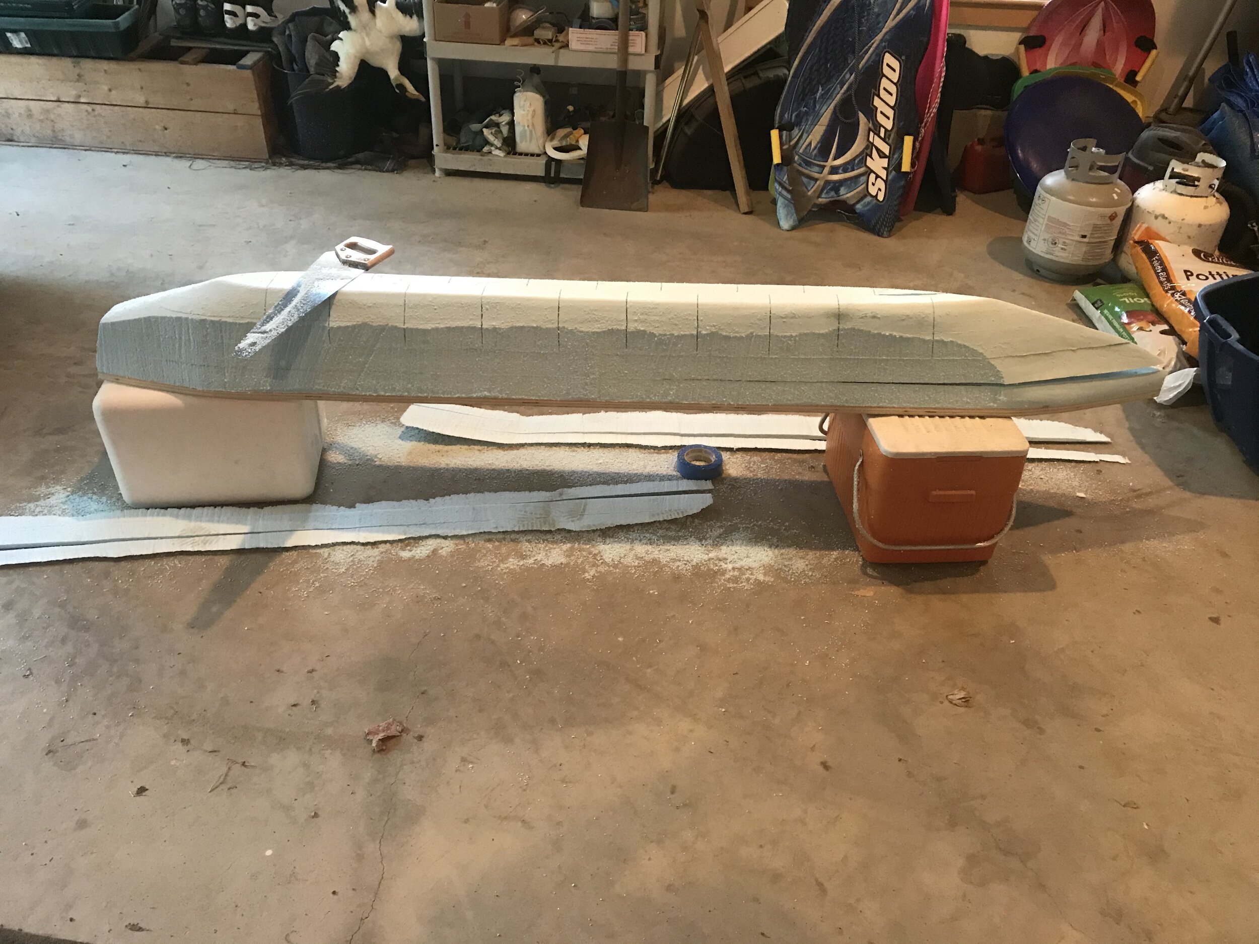


Upon mounting the unfinished outrigger to the canoe for a quick test, I discovered immediately that although I had cut a pretty sharp keel into the outrigger, it was nowhere enough to keep the boat tracking straight. I would either need to fit a keel, or find a way to mount a centerboard to the side of the outrigger or the canoe to get better tracking.
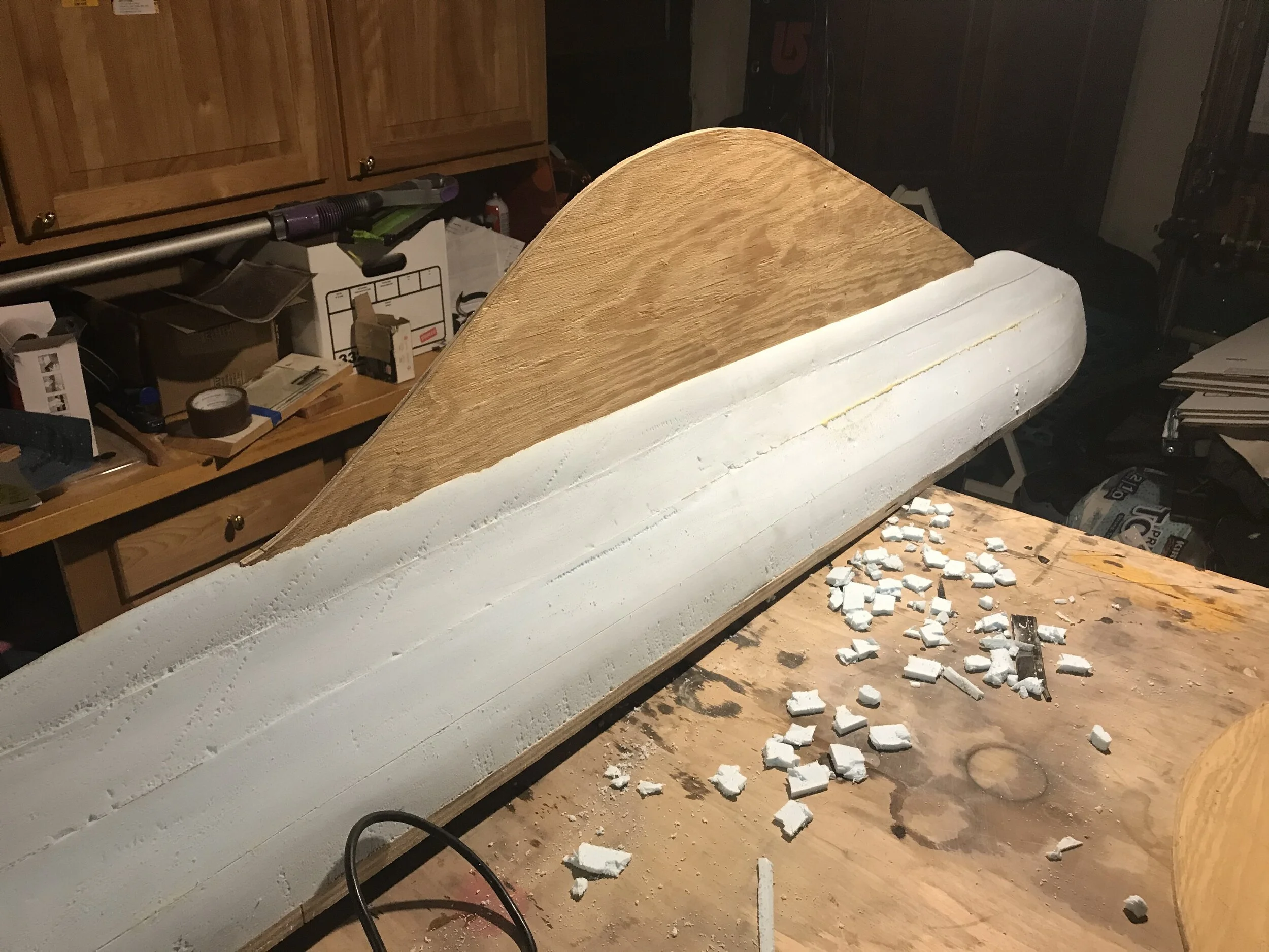
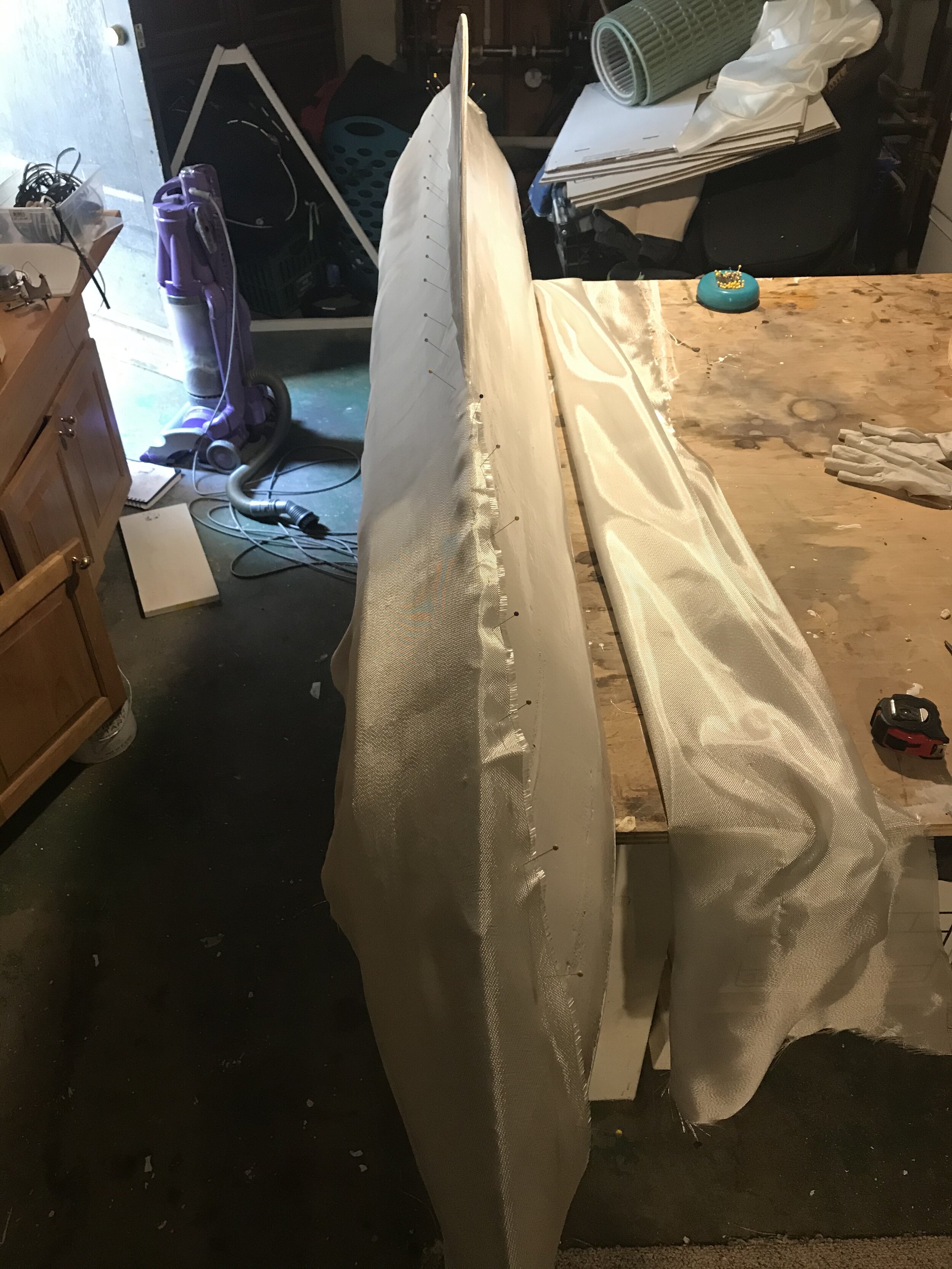
Since the outrigger was still unfinished, I mounted a keel in it and then fiber glassed the whole thing.


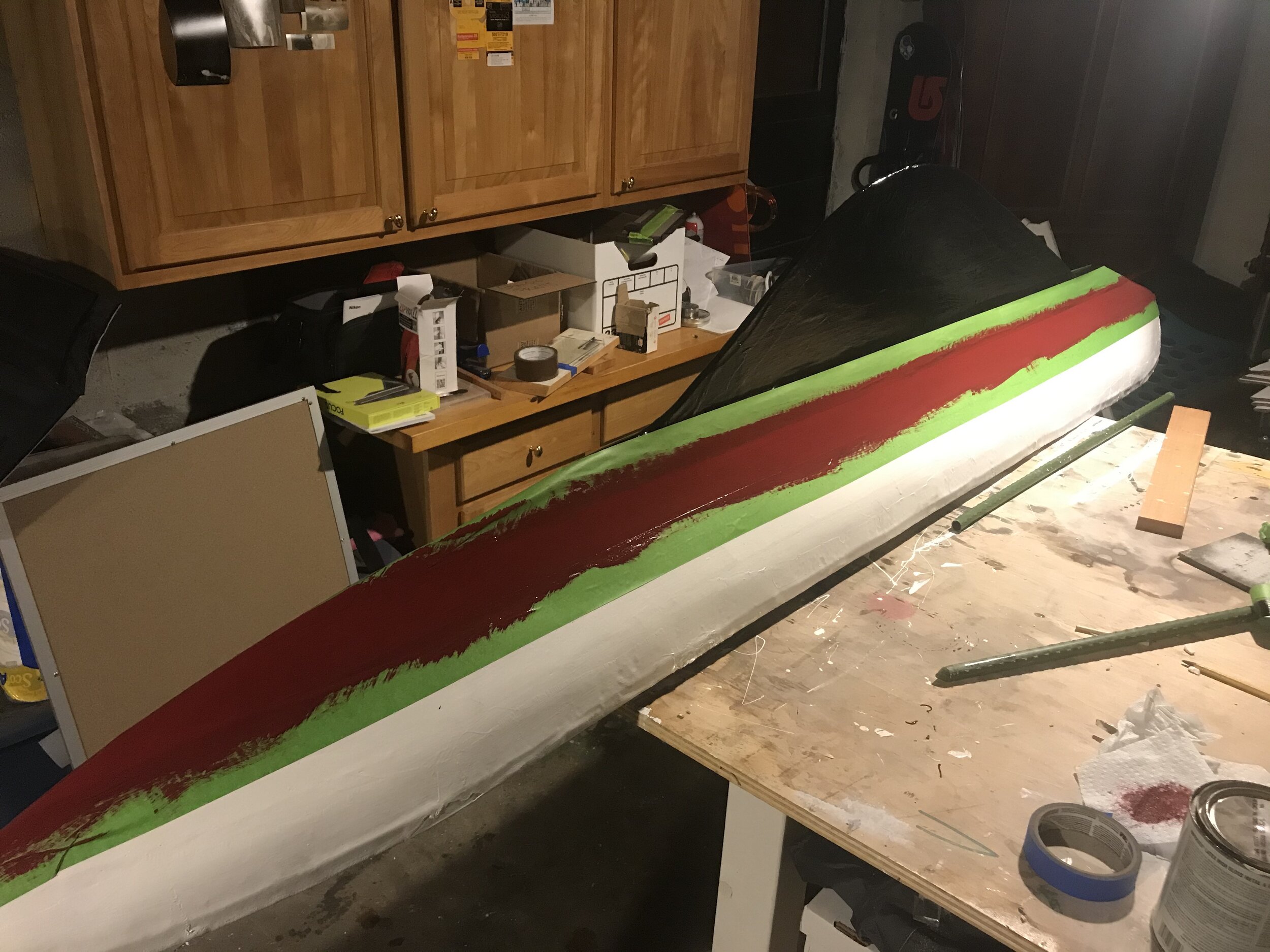
Next was a little paint.


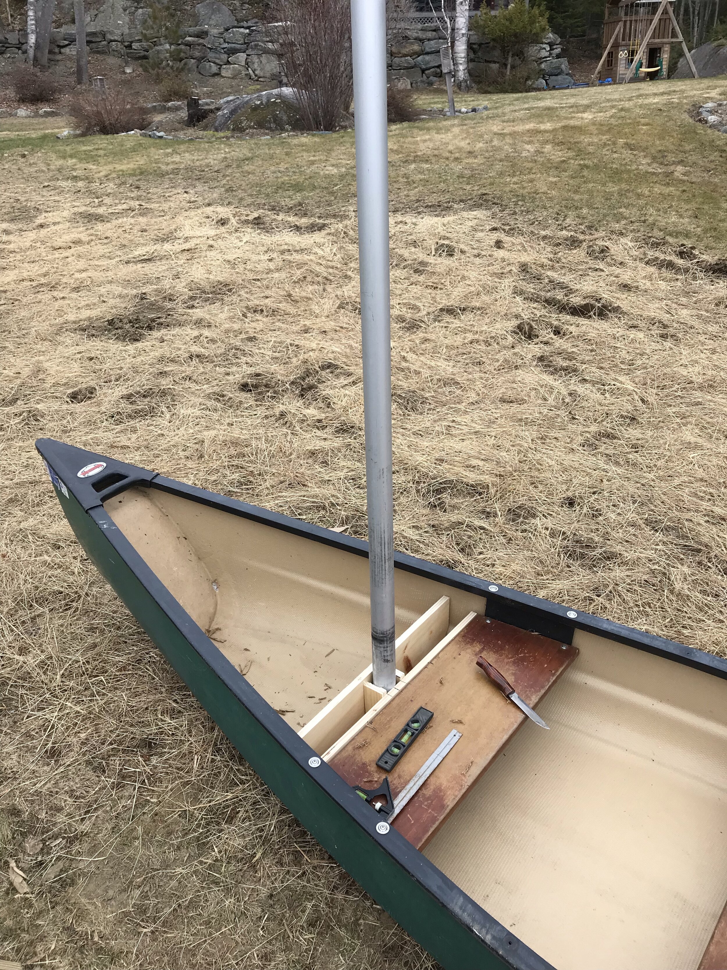
Jumping back in time, I also started work on the sail rigging adaptors to the canoe. This was pretty straightforward, and I just took a second-hand rigging from an old sunfish and built some mast footing and outrigger bar holders for the canoe. For the outrigger bars I went with 1/2 inch steel conduit piping, as it can be clamped firm to the boat and outrigger, but has a fair amount of flex. This was a mistake that anyone with a background in either physics or sailing would realize. Ill mention that later in the Mk. 2 project…

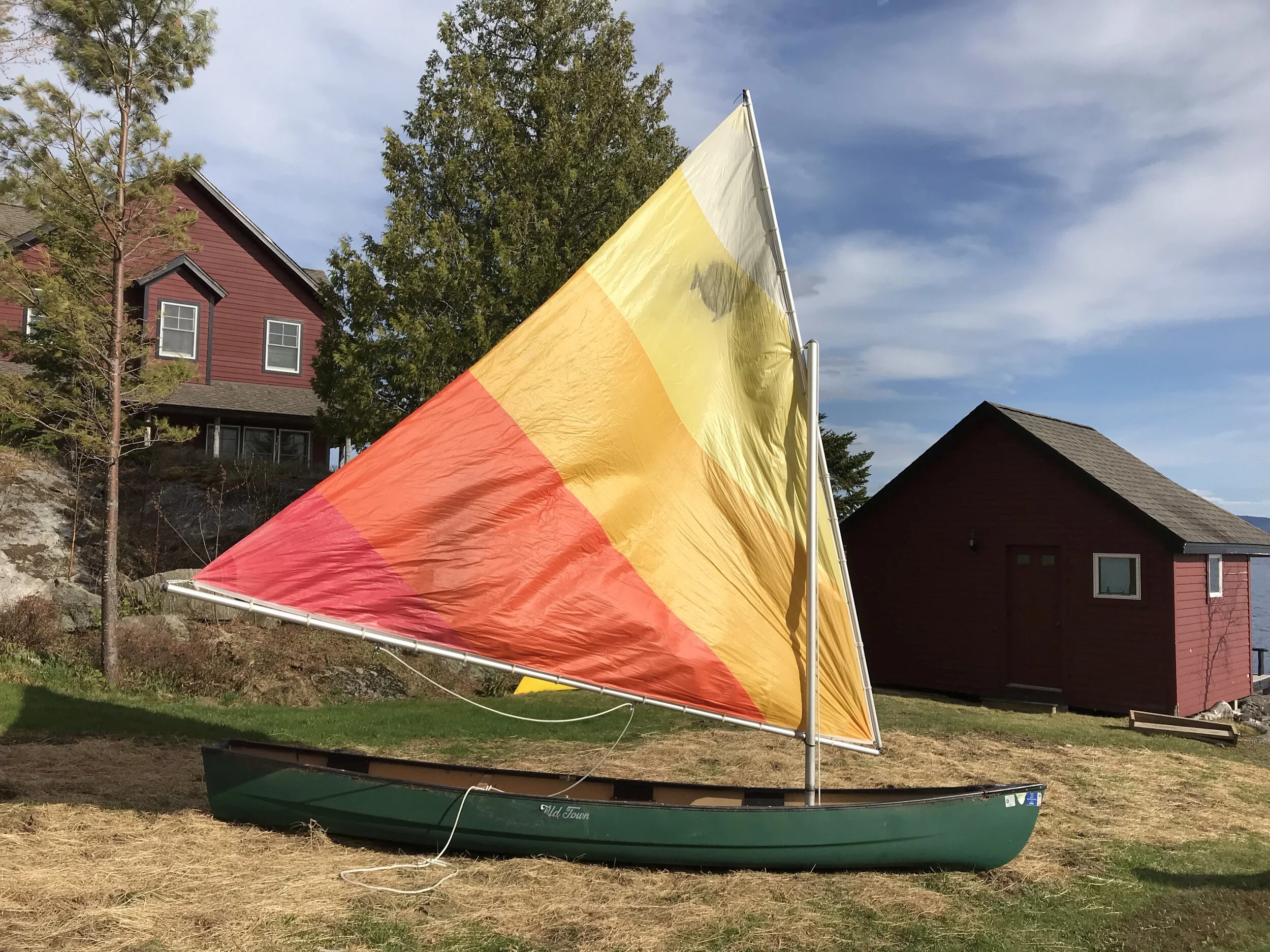


In 2020, it was time for a very gentle first sail:

Followed by some more shakedown sails in 2020, and finally being a bit braver, I brought it out in some firmer conditions in 2021.
Immediately 2 things became apparent. Firstly the mast footing was not strong enough for the sail forces, and started flexing. and secondly, the flexible conduit piping showed itself as being woefully under strengthened for any loads. The good news though was that the outrigger both floated, and made the boat track extremely straight. So not all bad news.
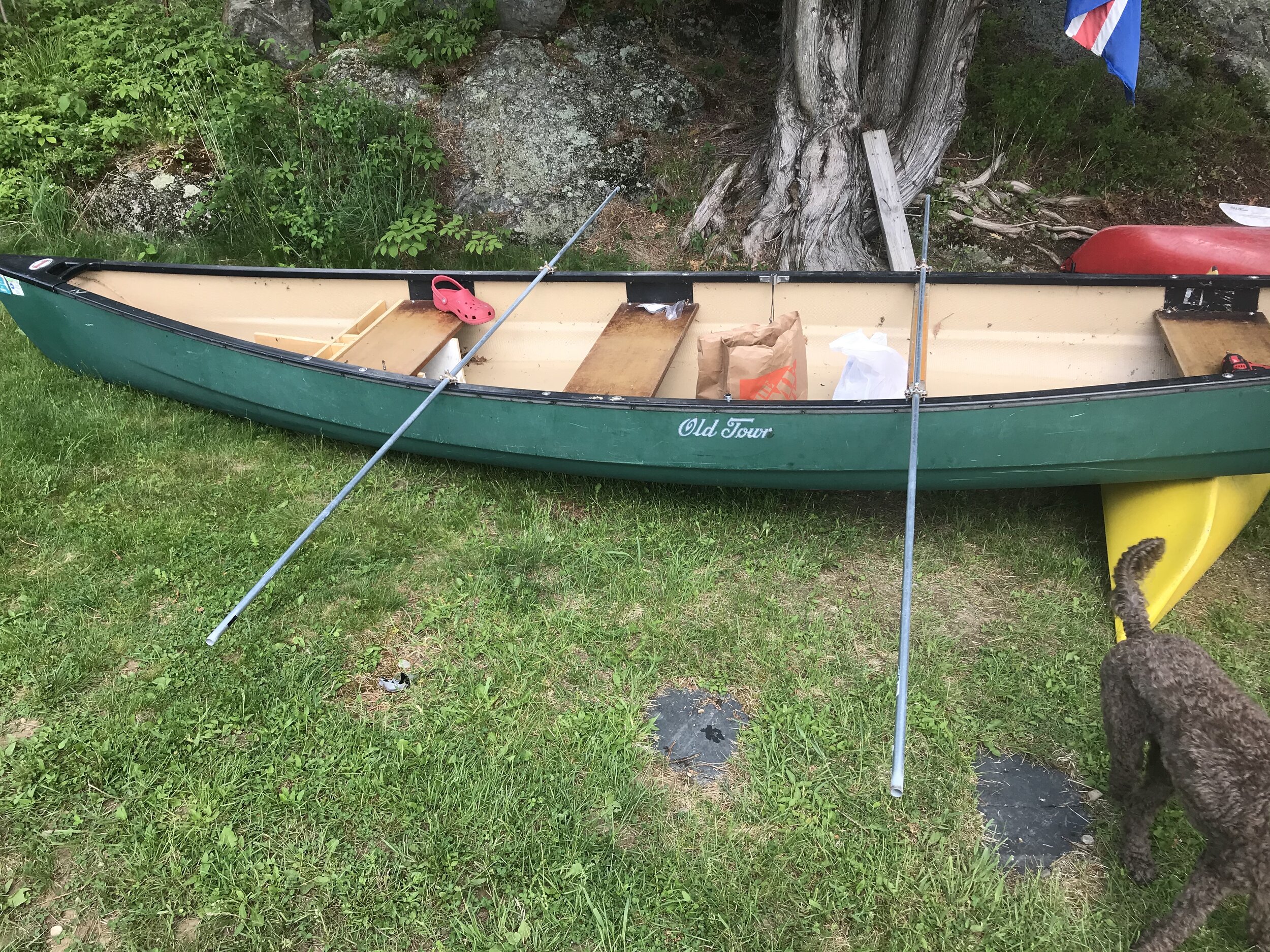
I decided then to replace the conduit piping with 2x4 lumber, and fasten it firm to the canoe gunwales. But how to fasten the pieces became a conundrum. for outrigger Mk 2 I cut notches in the 2x4s, and fitted them over the gunwales, bolting through the top of the notch as can be seen below (with a very handy shop assistant doing all the hard work).

This also was a bad idea, as I had once again ignored the physics of sailing.
Quick simple lesson (that I should have learned before all this):
When wind hits a sail, it does a few things. One of these is to rotate the mast in a parrallel direction to the wind. In a mono-hull, this rotation makes the boat lean (or ‘heel’ in sailing terms). This is not a problem, as sailboats are designed to heel over, and have heavy weights on their keels to counteract the heel. In smaller boats such as the sunfish that this sail rigging came from, the heel is counteracted by the body weight of the sailor leaning in the opposite direction of the heel. That’s why you always see sailors sitting on one side (the upwind side) of a sailboat.
This is all pretty straightforward. But what happens if you put an outrigger pontoon on one side of a mono-hulled sailing boat? Now, instead of the heel being counteracted by the weight of the sailor or a keel, it is entirely combatted by (on one tack) the weight of the outrigger which resists being lifted out of the water, or (on the opposite tack) the buoyancy of the outrigger which resists being submerged by the rotation of the sailboat. In effect, you have made a boat which cannot lean. but - that force on the sail is still there, and it is still acting on the boat trying to lean it over.
This puts a tremendous amount of strain on the arms which connect the outrigger with the main hull, especially at the exact spot where those arms are secured to the gunwale. On a tack where the outrigger is being lifted out of the water, the entire weight of the outrigger is resting on that point, trying to snap the arms downwards. Usually this is the easier of the two forces, because the outrigger is only so heavy, and the arms can usually cope with it.
On the other tack however, when the outrigger is downwind of the main hull, the force is trying to submerge the outrigger, and the strain is put on the arms to resist this. at best the arms will flex, and the sailor will be smart enough to keep an eye on the outrigger and arms to stop too much pressure from being put on them. At worst, two things can happen. Firstly, the arms, or the connections from the arms to the main hull, give way. The likely result being an immediate capsize and a very broken boat. Secondly, the arms can hold, but the buoyancy of the outrigger can be overcome, and the outrigger will be forced underwater. The sudden change in drag and pitch of this usually results in something referred to as a ‘pitchpole’, where the boat flips violently over forwards, as can be seen at 1:00 in the below video.
To avoid these scenarios, it is absolutely crucial that the arms between outrigger and sailboat are as strong as possible. It is also important that the outrigger be designed with a bow that resists being submerged. I considered neither of these things when building my boat.
In my sailboat Mk 1, the flexibility of the conduit piping certainly meant that pitchpoling and snapping of the arms was unlikely, but at the cost of any structural rigidity. It is no use having an outrigger if the arms bend in half as soon as some wind hits it.
In the video below, you can see the arms of Mk 2 holding up well when the outrigger is on the upwind side, and is being lifted up out of the water.
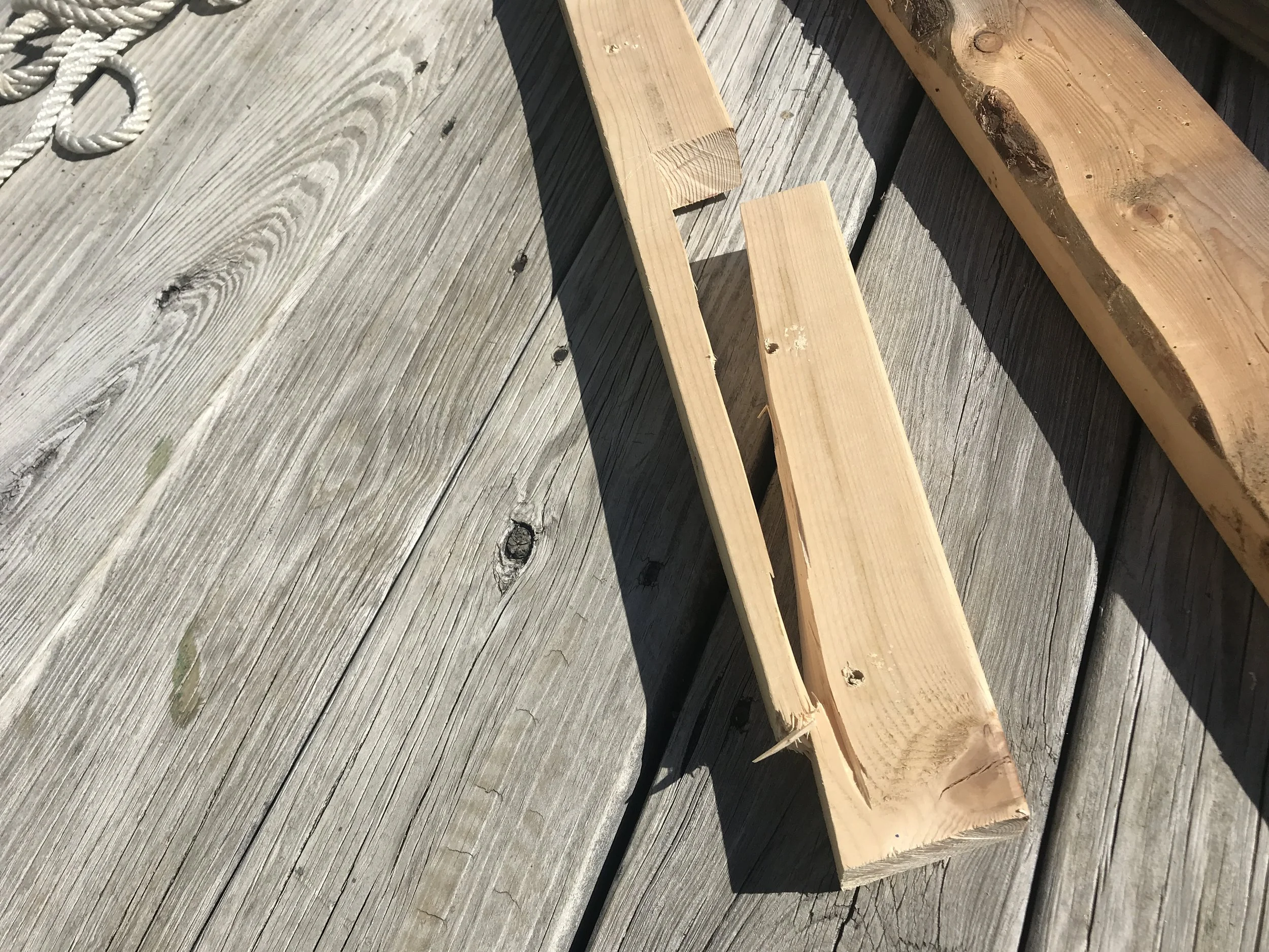
When the outrigger was on the downwind side of the boat however, it was a different story. The rotational stress concentrated on the connection point between arm and hull, with predictable results. In the below video, you can see if you look closely that the wooden arms are flexing across the port gunwale of the boat from the force of the outrigger resisting being submerged. And this is in light winds!
And here (luckily on land) is the result.
The lessons learned meant that for Mk 3, I connected the arms (still using 2x4s) to the main canoe using the oldest technology in the book: rope lashing. The lashing meant that the wood stayed in one piece, eliminating weak points, and there was just enough flex to allow slight movements and settling. The lashing also shrunk as it got wet, making for an extremely secure connection.
Part 2
Having had my fun with the canoe project, I decided to do two things. Firstly, to continue honing in on the optimum removable outrigger design for the freighter canoe, while simultaneously starting work on a bespoke sailing canoe from scratch.
In late 2021 I moved to a new place, and once the workshop is all set up, the boat building will commence. The better news here is that I’ve found some great resources and plans to follow for the canoe project, and have settled on a design style that I’ll follow. I’ll be using Gary Dierking’s wonderful and instructive book “Building Outrigger Sailing Canoes” for my design.
You can see a teaser of my chosen design below:
